Before you can add a Receiver to the Manitou system, you must connect and configure at least one FEP (Front End Processor). FEPs receive signal data from Receivers and forward it to Manitou. When an FEP or Receiver is physically connected to Manitou, you must configure at least one Receiver Line Prefix. All Manitou systems require at least one Receiver Line Prefix.
Receiver Line Prefixes allow Manitou to accomplish the following:
- Collect signal data from multiple Customer Transmitters and group it in a logical manner
- Collect data from primary and secondary Receivers and FEPs
- Provide a means of supporting duplicate Transmitter numbers within a system
Adding an FEP
Perform the following steps to add an FEP to Manitou:
- Navigate to the Maintenance menu, click "Setup" then click "Receivers".
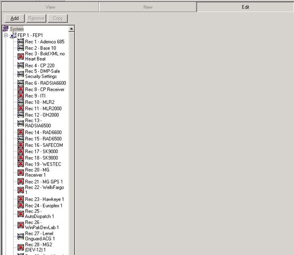
Result: The "Receivers" form displays as shown in the following screenshot:

- Click "Edit".
- Click the "System" icon in the list, then click "Add".
Result: The "Add FEP" window displays as shown in the following screenshot:

- Enter a description into the appropriate field.
- Select a starting number from the "Starting Number:" dropdown menu.
Note: The Starting Number is preselected based on the number of FEPs already configured.
- Select the number of FEPs you want to add from the dropdown menu and click "OK".
Result: Your new FEP now displays in the System list.
Adding a Receiver
A Central Station may have any number of Receivers based on the size of their business and the number of accounts being managed. Receivers are connected physically to the network based on manufacturer specifications. The Receiver is then connected either to the FEP directly or to a Digibox which acts as a hub for multiple Receivers and relays the signals to the FEP.
- Navigate to the Maintenance menu, click "Setup", then click "Receivers".
Result: The "Receivers" form displays as shown in the following screenshot:
- Click "Edit".
- Click on an FEP icon from the FEP list, and then click "Add".
Result: The "Add Receiver" window displays as shown in the following screenshot:
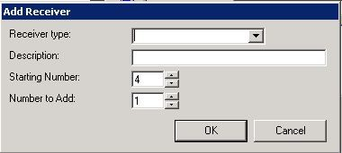
- Select a Receiver Type from the dropdown menu.
- Enter a description for your new Receiver into the "Description:" field.
- Select a starting number from the "Starting Number:" dropdown menu.
Note: The Starting Number is preselected based on the number of Receivers already configured.
- Select the number of Receivers you want to add from the dropdown menu, and click "OK".
Result: Your new Receiver is now displayed in the System list.
Adding and Grouping Receiver Lines
Each Receiver needs 2-8 Receiver Lines to receive signals (depending on type). Receiver Line configuration refers to the physical connections on a Receiver. Receiver Line Prefixes are assigned numbers used to identify a particular set of Customer accounts or a specific Dealer's Customers.
Perform the following steps to add and group Receiver Lines:
- Navigate to the Maintenance menu, and click "Setup", and then click "Receivers".
Result: The "Receivers" form displays as shown in the following screenshot:

- Click "Edit".
- Select the Receiver to which you want to add a Line from the FEP list, and then click "Add".
Result: The "Add Receiver Line Map" window displays as shown in the following screenshot:
- Select a Receiver Line Prefix from the dropdown menu.
Note: Ask your Central Station IT staff to assign you this number.
- Enter a description for the Receiver Line into the "Description:" field.
- Enter a starting number into the "Starting Number:" field.
Note: The Starting Number is preselected based on the number of Receiver Line Prefixes already assigned to other Receivers.
- Enter the number of lines you want to add in the "Number to Add:" field.
Note: This is determined by the number of Lines your new Receiver includes.
- Click "OK".
Result: The Receiver and the Lines associated with it now display in the FEP list, and the system displays the "Receiver Line Maps" form.
- If you want to designate a monitoring group, select it from the "Monitoring Group:" dropdown menu.
- If you want to designate an extended reporting delay, enter the number of seconds you want the delay to last in the "Extended Reporting Delay:" field.
Note: The extended reporting delay is the time in seconds the Driver waits for a second round of alarm information. When received, the system combines alarm information received in the second round with information received in the first round to form one signal. An extended reporting delay is only relevant regarding older signaling protocols (typically, protocols with a 3-4 digit account field and a 1-digit code field).
Note: The Manitou Supervisor Workstation allows you to modify the Line number of a signal as reported by the Receiver. This allows you to group signals from different Receivers together into a Line Group.
- If you want to group signals together into a Line Group, select the "Map Line" checkbox. In the "Map Line Number:" field, enter the number for the line to which you want the current Line to map. For example, the screenshot above displays the Line map settings for Line 2 on Receiver 11. If you want Line 2 to map to Line 1 (i.e., create a Line Group on Line 1), enter "1" in the "Map Line Number:" field.
- If you want the line to use DNIS for the Line, select the "Use DNIS" checkbox.
- Click "Save".
Adding a Receiver Line Prefix
Receiver Line Prefixes provide Manitou with information about the origin of received signals and the Customer accounts associated with them. Also, adding Receiver Line Prefixes increases the number of incoming signals that can be handled by a single Receiver.
- Navigate to the Maintenance menu, click "Setup", then click "Receivers".
Result: The "Receivers" form displays as shown in the following screenshot:
- Click "Edit".
- Select the Receiver Line Prefixes icon from the FEP list, and click "Add".
Result: The "Add Receiver Line Prefix" window displays as shown in the following screenshot:
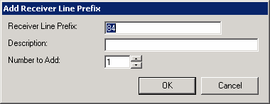
- Enter a description of your new Receiver Line Prefix into the "Description:" field.
Note: The "Receiver Line Prefix:" field displays prepopulated, and is determined by the number of Receiver Line Prefixes already entered into Manitou.
- Enter the number of Receiver Line Prefixes you want to add in the "Number to Add:" field, and click "OK".
Result: The "Add Receiver Line Prefix" window closes and the system returns the user to the "Receiver Line Prefixes" form.

- Trigger 1 and Trigger 2 fields may be left blank as they are not currently implemented.
- Enter the maximum number of Customers to be associated with the receiver line into the "Max Customers:" field.
- Enter the maximum number of Open/Close Customers to be associated with the Receiver line into the "Max O/C Customers:" field, and click "Save".
Transmitter ID Options (RLP and DNIS)
You have the ability to limit the number of characters read for when you receive an account. And, you have the ability to pad or even limit the TXID.
- maxtxid={Number} – If you are not using the option under the Receiver , RLP or DNIS options, then nothing is done with the TXID. If you choose this as the only RLP or DNIS option, then Manitou will cut off the TXID and take the numbers to the right. For example: MAXTXID = 4 and the TXID is 123456, the TXID will be parsed as 3456. If the MAXTXID = 4 and the TXID that comes through is 123 then the TXID will parse as 123 since it is less than 4 digits.
- txtrimpos={left/right} – This affects which side Manitou trims from if the TXID is longer than the maxtxid. It defaults to right if this is not set. If it is set to left, Manitou takes from the left side.
- txpadchar={character} – If this is set, Manitou assumes that if a string is shorter than the maxtxid, you want it padded. Manitou will take this character and pad it on the left-hand side before the numbers. Whatever character you use, Manitou will put it into uppercase.
Note: If this is set to 0, Manitou treats it as if it is not set at all because the system strips leading zeros everywhere else in the client.
- txpadpos={left/right} – If this is set /and/ a txpadchar is set, Manitou will put the padding at the side of whatever is defined. If the customer has it set to right, Manitou will put padding characters to the right-hand side of the TXID. Otherwise, they will go to the left-hand side of the characters.
So, if you have only maxtxid=6 and txpadchar=A, when a signal comes in as:
1234 -> AA1234
1234567 -> 234567
If you have maxtxid=6, and txpadchar=A, and txtrimpos=left, and txpadpos=right, when a signal comes in as:
1234 -> 1234AA
1234567 -> 123456
See the following screenshot as an example:

You set up the new Options on individual Receiver Line Map or DNIS Map. To set up Options on a Receiver Line Map or DNIS MAP, do the following:
- Open the Manitou Supervisor Workstation and click Maintenance | Setup | Receivers.
- Expand Receivers Line Maps or DNIS Maps and click the individual Receiver Line Map or DNIS Map to which you want to add the options.
Note: The option is comma delimited, for example, maxtixed=4,txtrimpos=left, txpadchar=$.